

진공관(Tube)이 등장한지 얼마 안된 시대에는 진공관이 상당히 고가의 부품이었으므로 최소의 사용으로 최대의 성능을 내야 했다. 그래서 개발된 것이 Reflex(반사) 방식의 수신기이다. 1개의 증폭기(Tube) 로 고주파, 저주파를 동시에 증폭하는 방식이다. 이 회로는 1914년 독일 과학자 Wilhelm Schloemilch와 Otto von Bronk가 특허를 처음 낸 것으로 알려져 있다.
https://en.wikipedia.org/wiki/Reflex_receiver
Reflex receiver - Wikipedia
From Wikipedia, the free encyclopedia Reflex receiver from the 1914 Schloemilch and Von Bronk patent.[1] The single triode vacuum tube amplifies the radio signal, then also amplifies the audio modulation signal extracted from it by the detector. A reflex r
en.wikipedia.org
트랜지스터가 만들어진 이후에도 여전히 Reflex 방식이 사용되었는데 흥미로워 보이는 Sinclair MICRO-6(1964년) 수신기 키트를 아래에 소개한다. AM 수신기로 3 TR 이며 당시 세계 최소형으로 광고되었다.

https://www.radios-tv.co.uk/wp-content/uploads/wpforo/attachments/751/6922=924-micro-6-general_1.JPG
아래는 상기 라디오에 대한 설명이다.
https://www.radiomuseum.org/r/sinclair_micro_6.html
Micro 6 Radio Sinclair Radionics Ltd.; St. Ives Cambridge, build |Radiomuseum.org
www.radiomuseum.org
http://rk.nvg.ntnu.no/sinclair/audio/micro-6.htm
Planet Sinclair: Radios: Micro-6
Micro-6 1964 The Micro-6, launched in 1964 at a price of 59/6d, was another matchbox-sized radio (though despite Sinclair's claims to the contrary, it was not the "Smallest Radio in the World" - devices launched as far back as 1959 were significantly small
rk.nvg.ntnu.no
회로를 간단히 설명하자면, 사용된 TR 은 MAT 100 시리즈 마이크로 합금 트랜지스터(게르마늄 트랜지스터) 로 알려져 있다. 2단 RF 증폭이 사용된 것은 아마도 초기 트랜지스터의 RF 성능 한계로 인한 것으로 추정한다.
아래 회로상에 특징적인 부분은 붉은 박스로 표시된 CW 이다.
이것은 Tr1 의 출력(컬렉터)에서 입력(베이스)로 RF 피드백을 제공하는 전형적인 기믹 캐패시터(gimmick capacitor) 이다. 잘라진 두 전선을 꼬아서 정전용량을 생성하며 일부를 잘라내거나 간격을 넓히는 것으로 용량이 조절된다.
AM 중파(MW) 주파수의 경우 수pf 만으로도 충분한 피드백을 제공하므로 이런 것으로도 충분하다.
이 피드백이 수신중인 신호와 동상(동일한 위상, 즉 Positive Feedback)일 경우 재생 방식과 동일하게 감도가 증가한다.
따라서 이 수신기는 Regen + Reflex 방식으로 추정 된다.

그리고 다음 모델인 Sinclair MICROMATIC 회로는 아래와 같다.(물론 이 라디오도 키트로 발매되었다.)
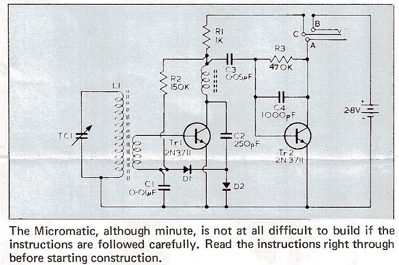
아래 MICROMATIC 키트의 부품구성은 MICRO-6 와 동일한 것으로 보이는데 왜 그런지 전후 사정은 알 수가 없다.
회로를 보면 알겠지만 MICROMATIC 으로 알려진 라디오는 실리콘 NPN 2 TR 구성이다.
TR 이 2 개(TO-92 타입의 Si NPN)로 줄어들고 Regen 을 위한 피드백 캐패시터가 사라진 것을 확인 할 수 있다. 그러나 아래의 설명에서 있듯이 이번에는 캐패시터를 통한 피드백이 아닌 초크코일 L3 를 통한 전자기결합 (ElectroMagnetic coupling) 으로 Regen 을 가능하게 한다. (초크코일과 바-안테나의 각도와 거리를 조정하면 재생 강도를 조절할 수 있다.)

https://www.worthpoint.com/worthopedia/sinclair-micromatic-am-radio-kit-270586396
Sinclair Micromatic Pocket Radio
Sinclair Micromatic Pocket Radio The Sinclair Micromatic was a two transistor AM pocket radio manufactured by the Sinclair Corporation. This was the world’s smallest pocket radio designed and marketed by Sir Clive Sinclair, one of the most successful Bri
www.petervis.com
https://k1.spdns.de/Vintage/Sinclair/Other%20Inventions/Micromatic%20Transistor%20Radio/
Sinclair Micromatic Transistor Radio
Sinclair Micromatic The Micromatic was introduced in 1967 and used the same tiny (45x34x15mm) case as its predecessor. Like the Micro-6, the Micromatic was available in both kit and ready made form. Unlike it's predecessor it used silicon transistors, whic
k1.spdns.de
The sinclair micromatic radio | PA4TIM's opvangtehuis voor buizenbakken
The sinclair micromatic radio On the Circuits online forum a man was rebuilding a Sinclair kit he bought many years ago. It dit not work back then and ended in the junkbox. See http://en.wikipedia.org/wiki/File:SinclairMicromatic.jpg for more info. He cou
www.pa4tim.nl
상기의 리플렉스 방식은 RF 증폭용 소자를 AF 증폭용으로 한번 더 재사용 한다는 점 외에 특별한 부분은 없지만 거의 비슷한 시기에 등장한 Regenerative(재생) 회로는 증폭기가 발진하는 부근까지 양귀환(Postive Feedback)을 걸어서 감도와 선택도를 높이는 방식의 수신회로 이다. 이 특별한 동작으로 인해 검파기의 감도를 1,700배 이상 증가시킬 뿐만 아니라 Q 가 증가하여 선택도가 올라간다. (아래 설명 참조)
https://en.wikipedia.org/wiki/Regenerative_circuit
Regenerative circuit - Wikipedia
From Wikipedia, the free encyclopedia Electronic circuit using positive feedback Homebuilt Armstrong one-tube regenerative shortwave radio with construction characteristic of the 1930s - 40s. The controls are (left) regeneration, (lower center) filament rh
en.wikipedia.org
재생 방식의 수신기에서는 AM 의 경우 자체 발진 바로 직전까지 피드백을 걸어서 수신하고, CW/SSB 등의 수신시에는 약하게 발진하도록 재생 강도를 조절하여 BFO 를 대체 할 수 있다. 따라서 재생 방식 수신기는 리플렉스 방식과 다르게 CW/SSB 를 복조할 수 있다. 또한 전통적인 재생 수신기 회로에는 검파기(다이오드)가 없다.
이러한 재생 방식 수신기는 에드윈 하워드 암스트롱 (Edwin Howard Armstrong, 1890년 12월 18일 – 1954년 2월 1일)이 고안한 것으로 알려져 있으며, 암스트롱은 이외에도 초재생 방식(Super Regenerative), 슈퍼헤테로다인(Superheterodyne) 수신기의 특허를 냈다. 그는 또한 FM 라디오의 발명자 이기도 하다. 개인적 생각으로는 현대 라디오의 아버지라 불러도 무방할 정도이다. 그래서 영미권에서는 앞서 나열한 방식의 수신기를 소개할 때 앞에 암스트롱을 붙여서 표기하는 경우가 종종 있다.
https://en.wikipedia.org/wiki/Edwin_Howard_Armstrong
Edwin Howard Armstrong - Wikipedia
From Wikipedia, the free encyclopedia American electrical engineer and inventor (1890–1954) Edwin Howard Armstrong (December 18, 1890[2] – February 1, 1954[3]) was an American electrical engineer and inventor, who developed FM (frequency modulation) ra
en.wikipedia.org
재생 수신기에서 발진 상태에 가까이 될 때까지 피드백을 조정하면 안정적인 작동 상태를 유지하기가 힘들게 된다. 수신 주파수가 올라가면 안정적인 수신을 하는 것은 더욱 힘들게 된다.
이런 단점을 극복하고 최상의 재생 감도를 얻기 위해 암스트롱은 초재생(Super Regenerative) 을 고안한다.
초재생은 재생 회로를 발진하는 상태로 피드백을 유지하고 별도로 정해진 간격마다 증폭을 중지(발진을 소멸시킴, 초재생에서는 Quench 라고 부른다.) 시킨다. 따라서 초재생 수신기는 재생 강도 조절 기능이 불필요하다.
이 작동은 사실상 샘플링으로 작동하는 증폭기이므로 퀜칭 주파수로 인해 수신 대역폭의 제한이 발생한다(나이퀴스트 이론). 따라서 재생 방식에 비하여 초재생은 수신 대역폭이 증가(선택도가 감소)하고, BFO 가 필요한 CW/SSB 등의 복조가 제대로 되지 않는 단점이 존재한다. 이 단점은 점유 주파수 대역폭을 넓게 사용할 수 있는 VHF 밴드 이상의 주파수에서는 큰 문제가 되지 않으므로 VHF 이상에서 AM 이나 FM 을 수신할 때 주로 사용하는 회로가 되었다.
이론상 재생회로든 초재생 회로든 앞단에 믹서(주파수 컨버터)가 붙을 경우에는 초재생이나 재생방식의 한계를 뛰어넘는 범위의 운용도 가능해지는데 실제로 초재생 + 슈퍼헤테로다인(주파수 변환 후 초재생으로 복조)의 수신기가 존재했다.
아래 링크에 해당 수신기의 역사와 실제 구현에 대해 자세히 설명되어 있다.
https://www.cool386.com/fremodyne/fremo1.html
Fremodyne FM receiver
The Hazeltine FreModyne FM Receiver (Part 1). Introduction Readers of Electronics Australia during the 1960's will remember their "Fremodyne Four" pr
www.cool386.com
현재 재생이나 초재생 방식 수신기는 상업 방송 수신용으로는 거의 사용되지 않으나 여전히 간단한 송수신기(차고 문 개폐 등의 간단한 무선 원격조작 스위치 등)에는 초재생 방식이 사용되고 있다.
아마추어 무선 영역에서는 취미 목적의 수신기 제작으로 재생 방식 수신기를 선택하는 경우가 종종 있다.
예를 들면 MFJ 에서는 아래와 같은 재생 수신기 키트(또는 완제품)를 판매하고 있다.
https://mfjenterprises.com/products/mfj-8100k
MFJ-8100K, WORLD BAND SWL RECEIVER-KIT
Remember hunching over your regenerative receiver for hours with a pair of phones pressing uncomfortably against your ears?You could hear just about anything that fancy superhets could hear. Sure, you had to play around with the regeneration control just r
mfjenterprises.com
Reflex, Regen, Super Regen 등의 수신기에 흥미가 있는 경우 아래 사이트들을 참고 한다.
리플렉스 수신기 회로 및 제작
https://skywaves.ar88.net/homebrew/reflex/Reflex%20Radio%20Receivers.html
Reflex Radio Receivers
A reflex radio is one in which a single amplifier is reused to first amplify an RF (or IF) signal, and then amplify the AF produced by a separate detector. As long as the amplifier operation remains linear, there is no interference between the RF and A
skywaves.ar88.net
1TR 단순한 재생 수신기
http://techlib.com/electronics/regen.html
Regenerative Receivers
Regenerative Receivers Regenerative receivers provide a surprising level of performance with only a handful of components. They excel at receiving amplitude modulated signals from below the AM broadcast band up to the higher short-wave bands above which th
techlib.com
또 다른 재생 수신기
http://www.robos.org/sections/radio/regen.html
Regenerative receiver projects
Regenerative receiver projects Lemon Drops This is a homebrew regenerative receiver, mostly based on several designs by Charles Kitchin N1TEV. See the links below for an article by him. The receiver tunes the entire 30m band (10100-10150) and performs quit
www.robos.org
VHF 밴드 초재생 수신기
https://www.cool386.com/6tr/srrx.html
6 Transistor VHF Super Regenerative Receiver
6 Transistor Super Regenerative Receiver. The following is a design for a separately quenched super regen receiver I first tr
www.cool386.com
2.4GHz 초재생 실험.
https://people.engr.tamu.edu/s-sanchez/665%20SRR%20Fall08.pdf