


Thanks for visiting my blog (from Google analytics)
For overseas OMs.
A sleeve dipole operating at the 3rd harmonic behaves like an EDZ.
This article shows a simulation of how it works. written by DS1ORJ.
※ 이 글의 내용을 인용할 생각이라면 반드시 출처를 밝히기 바란다. DS1ORJ
A classic example of a multiband dipole.
The fan dipoles are all connected to the feed point.

However, the open sleeve dipoles are not connected and placed in parallel.

The antennas described below are 7, 21 dual band dipoles.
One is a fan dipole and the other is an open sleeve.
The fan dipole is 20.4m + 6.8m parallel connection.
The open sleeve dipole is 21m + 6.8m parallel arrangement.
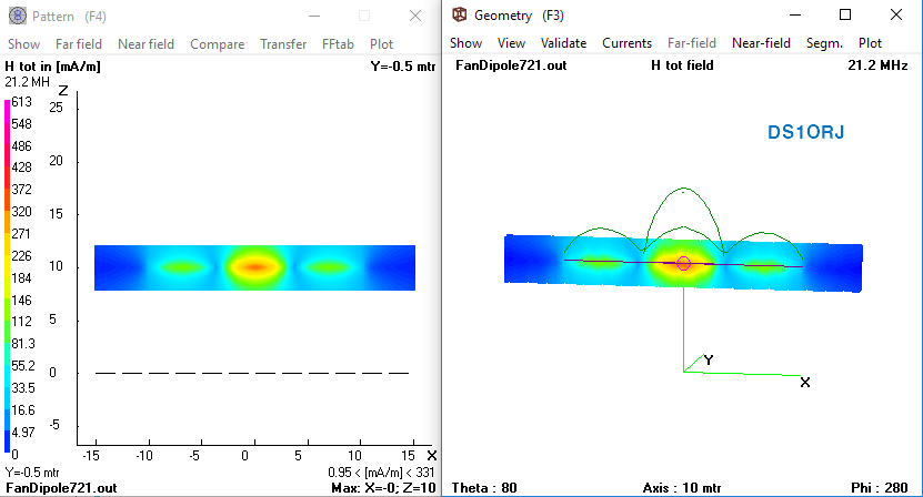
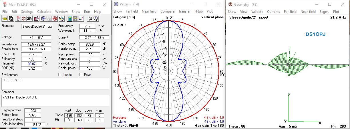
Below is a 7/21 fan dipole feeding 21 MHz.
Most of the current is concentrated in the 21 MHz element.
The dipole also works on the 3rd harmonic, so it also radiate a 7MHz fundamental element.
result is a distortion of the pattern.

The gain is 1.77 dBi, but when calibrated by AGT -0.2 expect a final gain is 1.95 dBi.
As expected, the element current distribution in the feeding section is concentrated in the 21MHz element.

Its near H field is shown below.
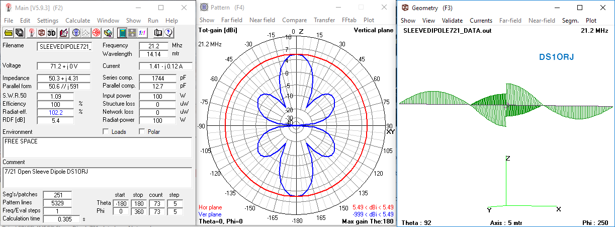
Now let's look at the open sleeve dipole.
Gain is 5.49 dBi (AGT of 0.09 dBi), we expect a compensation gain of 5.4 dBi.
Incredible gain. this is not a calculation error.
This is about 3 dB higher than the 2 dBi of the fan dipole. (continue to explain why this is so)
Since the current distribution flows in the reverse direction by the sleeve wire at the center, the central radiation is canceled (zero sum).
main radiation occurs at both ends. Radiation occurs at both ends of the element (1/2 wave + 1/2 wave).
Unlike the fan dipole, you can see that the current flows through the 7 MHz element and the 21MHz open sleeve wire together. (The open sleeve is two lines, each with half the current)
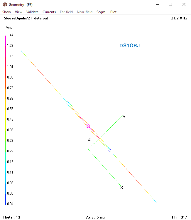
This current flow is equivalent to a 1.5 wavelength sleeve antenna (like J-pole).
If two 1.5 wave sleeve antennas are connected, the operation is the same as that of a 3rd harmonic open sleeve dipole antenna.
Don't worry about the phase of the current. It is only displayed depending on the wire direction.
This is a feature of NEC and does not affect the results.
Balanced antennas are inherently incapable of in-phase feeding.
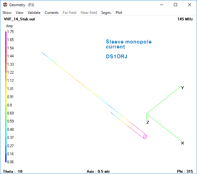
To explain the principle more clearly.
We can cross connect two sleeved monopoles to make a dipole and it works the same as an open sleeved dipole.
This is a demonstration dipole made of two monopoles. Gain is 5.3 dBi (AGT -0.4 dB)
Since there are two sleeve monopoles spaced 1/2 wavelength apart, +3dB gain can be expected.
A single sleeve antenna is about 2.64 dBi, so 5.64 dBi. Actually simulated as 5.3 dBi
Thus, the actual operation of a sleeve dipole operating at the 3rd harmonic would be 1/2 wavelength + 1/2 wavelength.
An open sleeve dipole operating at the 3rd harmonic is like to an EDZ antenna (called Extended Double Zepp)
Below is the radiation pattern compared to EDZ.

http://www.antentop.org/w4rnl.001/mu3a.html
THE EDZ
MODELING AND UNDERSTANDING SMALL BEAMS PART 3: THE EDZ FAMILY OF ANTENNAS L. B. Cebik, W4RNL The Extended Double Zepp (EDZ) has been a lonely antenna for most of its life, since Hugo Romander, W2NB, introduced its potential to the amateur community in 1938
www.antentop.org
Now look at the near field of the actual EDZ antenna.
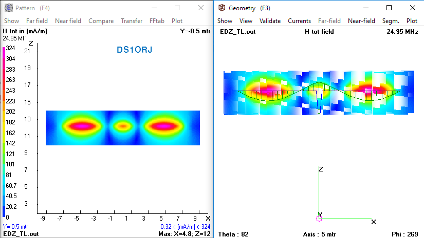
Its H field radiation is at both ends.
And the open sleeve antenna?
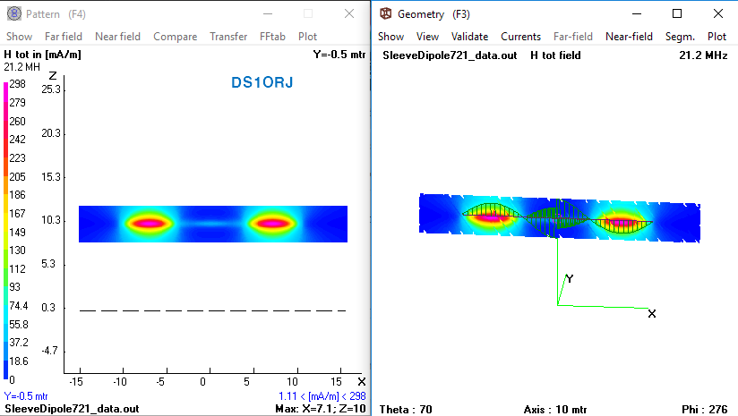
Yeah it's about the same. IMO sleeve antenna looks better than EDZ.
We imagine that the main radiation will occur in the center, but it works differently than we think.
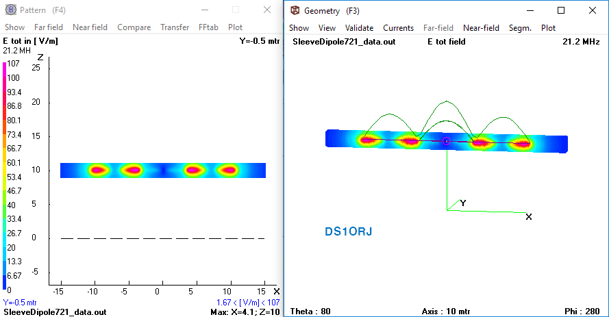
you can see very little center radiation, next is E field.
Below is the H field of the fundamental frequency(7 MHz). It seem to be just a dipole.
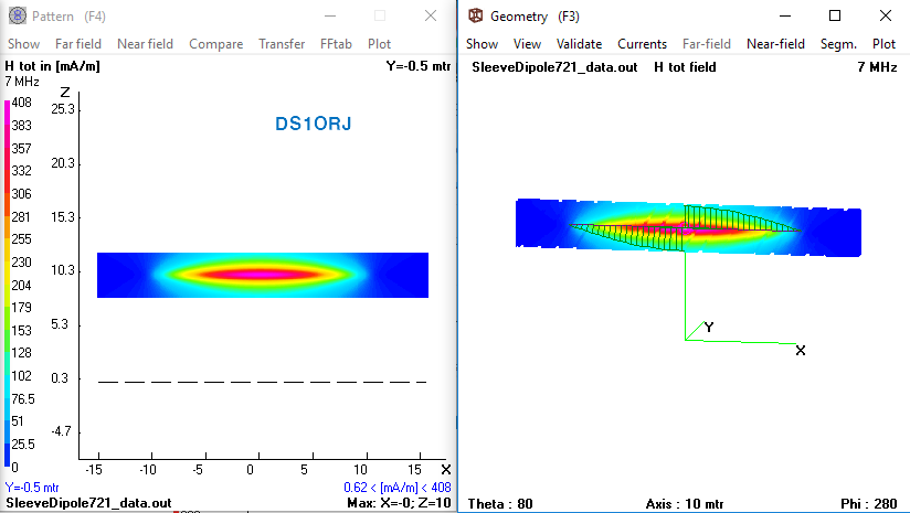
Advantage is that it does not require a ladder line feeder.
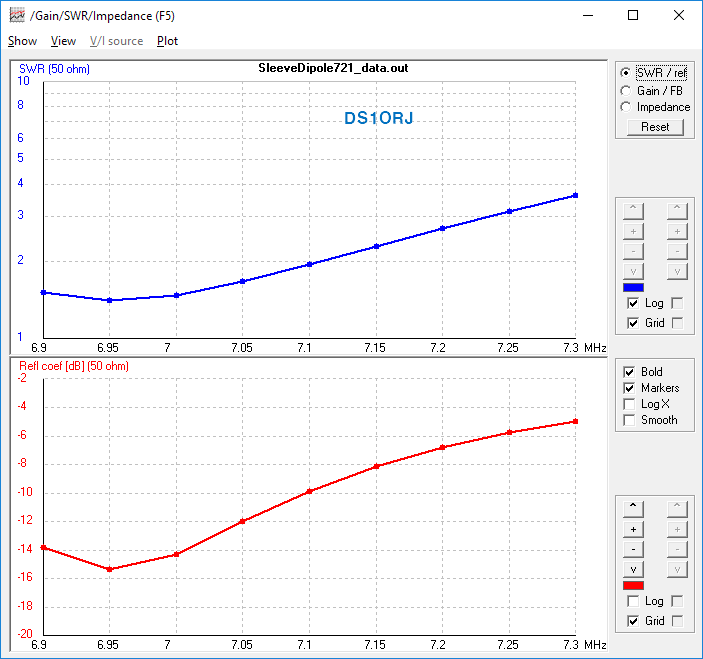
The only downside of this antenna is its narrow bandwidth at the 3rd harmonic and difficult tuning.
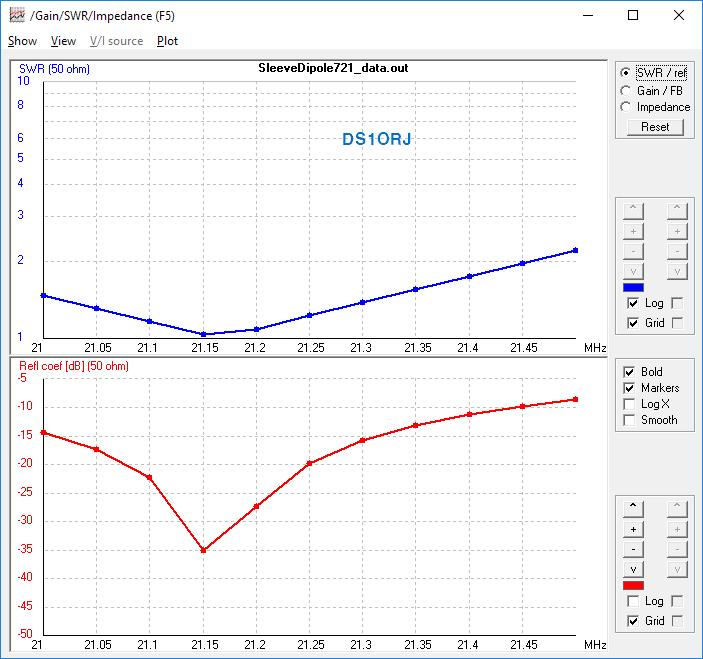
At the 7MHz fundamental frequency, it fits on the lower side. it's not good.
However, it provides a usable range with a tuner.
3rd harmonic open sleeve antennas will work.
It is like two J-poles or EDZ antennas.
Age-old debate.
https://www.eham.net/article/8808
eHam.net
I was going to say something about the feedline issue too, but I thought surely I must be missing it somewhere? So, how would you feed this thing? And, specifically, how would you feed it with coax? K5DVWReply to a comment by : WB2WIK on 2004-07-22I still
www.eham.net
You can see it in the flower pot antenna.
https://vk2zoi.com/articles/dual-band-half-wave-flower-pot/
Dual Band Half-Wave Flower Pot Antenna – VK2ZOI
Dual Band Half-Wave Flower Pot Antenna The basic half wave version of the Flower Pot antenna can be readily modified to dual band the antenna for operation on a band that is the (approximate) third harmonic of the fundamental resonance. Operation on the th
vk2zoi.com
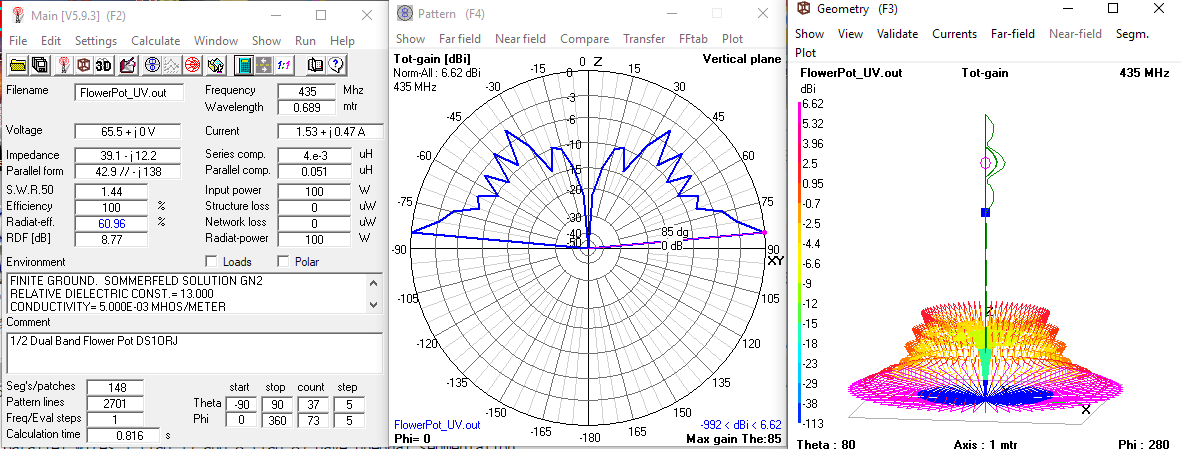
This is a 435MHz simulation of the flower pot antenna.(Simultaion used open sleeves).
And real world.
https://ds1orj.tistory.com/143
Flower Pot Antenna (화분 안테나) 제작
설명 편의상 존칭은 생략 합니다. 이 안테나의 방사패턴 시뮬레이션은 아래 글을 참고한다.( 2022.11.19 4NEC2 시뮬레이션) https://ds1orj.tistory.com/206 Flower Pot 화분 안테나 성능 시뮬레이션 화분 안테나
ds1orj.tistory.com
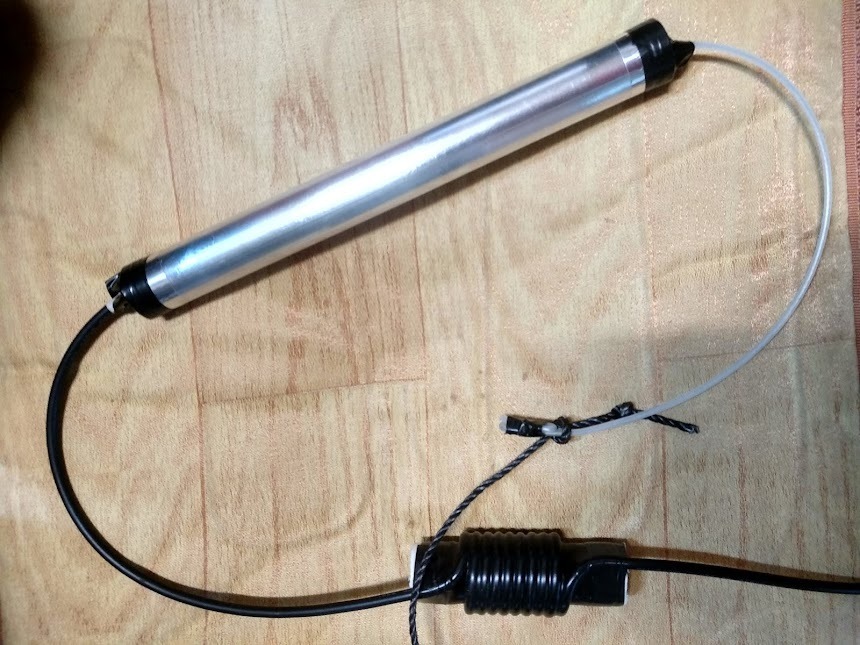
I made and it worked fine.
Please email us with any questions.
codeart74@daum.net
thanks. 73.
Published by DS1ORJ on 2022.11.23.